Fiber-reinforced polymer (FRP) systems, particularly those using carbon fiber (CFRP), are widely adopted for strengthening existing concrete structures. While externally bonded CFRP can significantly increase flexural and shear capacity, its effectiveness is often limited by premature debonding from the concrete substrate. In many design scenarios, especially when high strain levels are required or when the substrate is weak, mechanical anchorage systems become necessary to delay or prevent debonding, allowing the CFRP to reach its full tensile strength. This article discusses the types of mechanical anchors used with CFRP sheets and strips, the principles of their action, and guidance on when and how to apply them in accordance with recognized design guidelines such as ACI 440.2R.
Failure Modes Addressed by Mechanical Anchors
The predominant failure mode for externally bonded CFRP is debonding, which can occur at the concrete-epoxy interface, within the concrete cover, or at the CFRP-epoxy interface. Even with proper surface preparation and adhesive selection, debonding initiates at high stress concentrations, often at the laminate ends or at flexural cracks. Mechanical anchors aim to suppress these debonding mechanisms by providing additional load transfer paths or by clamping the CFRP to the substrate. Without anchorage, the effective strain in the CFRP is limited to about 0.5–0.7% by design codes, whereas mechanical anchors can enable strains approaching the material’s ultimate capacity (typically >1.5%).
Types of Mechanical Anchors for CFRP
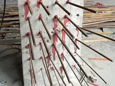
FRP Spike Anchors (Tow Anchors): These are made of bundled carbon fiber tows saturated with epoxy, inserted into a pre-drilled hole and fanned out over the CFRP surface. The anchor transfers load from the CFRP into the concrete through bond and mechanical interlock in the hole. They are relatively easy to install and suitable for both sheets and strips, providing three-dimensional confinement to the laminate.
FRP U-Wraps with Anchorage: For shear strengthening or flexural end anchorage, U-wraps that extend around the section can be combined with embedded anchors or horizontal strips to prevent peel-off. These are effective for beams and columns, often paired with groove anchoring at the ends.
Steel Plates and Bolts: Mechanical fasteners such as steel plates bolted through the CFRP into the concrete provide a direct force transfer mechanism. These are used at laminate ends or at critical sections, but require careful detailing to avoid crushing the CFRP and to accommodate thermal effects.
Groove Anchoring (Near-Surface Mounting): A variant is to embed the ends of the CFRP strip into a shallow groove cut into the concrete, filled with epoxy. The groove provides lateral confinement and mechanical interlock, significantly improving the development length compared to surface bonding alone.
Design Considerations and Placement
Mechanical anchors are most effective when placed at the ends of CFRP laminates to prevent end debonding, or at intermediate locations to control intermediate crack-induced debonding. The number, spacing, and embedment depth of anchors must be designed to develop the required force. For spike anchors, the diameter of the anchor (typically 6–12 mm of bundled fiber) and the embedment depth (usually 50–75 mm) govern capacity. Steel plates should be designed to avoid bearing failure of the CFRP and to distribute clamping forces evenly. Guidelines such as ACI 440.2R provide design equations for anchor capacity based on concrete strength and anchor geometry, with partial safety factors applied.
Placement rules: Anchors should be located at least 25 mm from the laminate edge to avoid edge splitting. For multiple anchors, spacing should not exceed 4× the anchor diameter or 6× the laminate thickness. In flexural strengthening, end anchors are often supplemented with shear anchors near the support to resist peeling stresses.
Installation Methods and Quality Control
Installation of FRP spike anchors: (1) Drill a hole of specified diameter (about 1.5–2 times the anchor diameter) into the concrete substrate; clean the hole thoroughly. (2) Saturate the carbon fiber tow with epoxy and insert to the required depth; allow the fan to extend over the CFRP surface (at least 75 mm). (3) Apply a second layer of epoxy over the fan and ensure full wet-out. For steel plates, holes are drilled through the CFRP (carefully to avoid fiber damage), and bolts are torqued to a specified value — typically with a soft washer to protect the composite. Quality control includes pull-off testing of anchors (concrete cone failure mode is preferred) and visual inspection of epoxy wet-out.
Code Compliance and Design Recommendations
Most international codes (e.g., ACI 440.2R, fib Bulletin 14) acknowledge mechanical anchorage as a method to increase the effective strain in CFRP for both flexural and shear strengthening. However, they emphasize that anchor capacity must be verified by testing or by established models. Designers should consider a reduction factor (typically 0.50–0.75) for anchor strength to account for installation variability. When anchors are used, the design strain in the CFRP may be increased up to 70–80% of the ultimate tensile strain, but never beyond the strain that would cause concrete crushing or shear failure in the original member. It is also critical to ensure that the anchor system is compatible with the adhesive system and that the CFRP itself can sustain the localized stresses without premature rupture at the anchor point.
Closing Remarks
Mechanical anchorage is a proven technique to unlock the full potential of CFRP strengthening systems, especially when substrate conditions are challenging or when high-strength utilization is required. By selecting the appropriate anchor type—spike anchors for sheets, steel plates for strips, or groove details for thin laminates—and following proper design and installation procedures, engineers can significantly delay debonding and enhance structural performance. Always consult current code provisions and, when in doubt, conduct representative testing to validate anchor capacity for the specific application.