
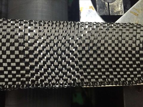
At a glance
- Two schemes, one limit: soffit plates carry flexure, web U-wraps carry shear — but the bond governs, not the fiber. In a 375-beam database, 100% of unanchored bonded beams failed by debonding (70% intermediate-crack, 30% end), none by fiber rupture.
- Bridges take a 15% exposure haircut: the environmental factor CE = 0.85 for carbon in exterior exposure vs. 0.95 indoors (ACI 440.2R Table 9.4), and CFRP shear strain is capped at εfe = 0.004 regardless of the fiber’s ~1.8% rupture strain.
- Anchorage is the design lever, not more layers: an unanchored U-wrap tops out near +25–27% shear gain; spike-anchored bidirectional CFRP reached +35.8% on a full-scale AASHTO Type IV prestressed girder.
Externally bonded CFRP strengthens a concrete bridge girder in two distinct ways — soffit-bonded plates add flexural capacity, web U-wraps add shear — but on a real bridge the bond, exposure factors, and anchorage detailing set the ceiling long before the carbon fiber approaches its rated strength. That gap is the whole story of a sound retrofit. This guide walks the practical design and installation decisions for RC and prestressed girders, grounded in ACI 440.2R-17 and full-scale test data. If externally bonded FRP is new to you, start with what CFRP strengthening is.
Why do concrete bridge girders need strengthening?
Three drivers dominate. First, rating deficiency — raised legal load limits, re-rating, or permit overloads push demand past the girder’s original capacity. Second, deterioration — chloride ingress, carbonation, and freeze–thaw corrode reinforcement and lose section. Third, impact damage — over-height vehicles strike prestressed girder soffits and webs. Externally bonded CFRP addresses all three without adding meaningful dead load or reducing under-clearance, which is why agencies such as Florida DOT have used it on bridges for over 20 years. The alternative — a bonded steel plate — weighs roughly five times as much (steel 7.9 g/cm³ vs. CFRP 1.5–1.6 g/cm³, ACI 440.2R Table 4.2.1) and reintroduces the very corrosion problem you are repairing.
How is CFRP used on a girder — flexure vs. shear?
For flexure, a CFRP plate is bonded to the soffit (tension face) in a 2–4 mm adhesive bond line; ACI 440.2R applies a strength-reduction factor ψf = 0.85 to the FRP’s moment contribution. For shear, CFRP fabric is wrapped around the web. On a bridge girder the deck slab blocks the top, so a true four-sided wrap is rarely possible — you get a three-sided U-wrap, which carries ψf = 0.85 against 0.95 for a full wrap (ACI 440.2R Table 11.3). The practical consequence: shear retrofits on girders are inherently anchorage-dependent, because the one side that would lock the wrap in place is unavailable.
Why does the fiber never reach its rated strength on a bridge?
Because the bond gives way first, and the code deliberately caps usable strain below rupture. For flexure, the debonding-strain limit is εfd = 0.41√(f′c / (n·Ef·tf)) ≤ 0.9εfu (ACI 440.2R-17 Eq. 10.1.1, calibrated by Teng et al.), and the effective design strain is εfe = min(εfd, 0.9εfu). For shear, a full wrap is limited to εfe = 0.004 ≤ 0.75εfu (to preserve aggregate interlock), and a U-wrap to εfe = Kv·εfu ≤ 0.004 with a bond-reduction coefficient Kv ≤ 0.75. A carbon fabric that ruptures near 1.8% strain is therefore designed to roughly 0.4% — less than a quarter of its capacity. The 375-beam evidence is blunt: every unanchored bonded beam debonded (70% intermediate-crack, 30% end), none reached fiber fracture.
Does a U-wrap need anchorage on a bridge girder?
Almost always, and the test data is emphatic. An unanchored, purely adhesive U-wrap tops out around +25–27% shear gain. Add correctly detailed spike anchors and a bidirectional layout and a full-scale AASHTO Type IV prestressed girder reached +35.8%. The direction of the fabric matters more than the anchor count: TxDOT full-scale tests found vertical strips with spike anchors alone gave a negligible +2% ultimate gain, while adding horizontal strips raised it to +33–36%. Spike-anchor practice from Florida research: hole depth 6 in. (4 in. minimum), fan angle 60°, and anchor sectional area at least twice the strip’s fiber area. ACI 440.2R also requires anchoring the ends of a flexural plate when Vu > 0.67Vc (Sec. 14.1.2), and continuous spans must extend the FRP at least 450 mm past the inflection point.
How much do exposure and fatigue cut the design values?
Stack the reductions in order. The environmental factor CE = 0.85 for carbon in exterior/bridge exposure (ACI 440.2R Table 9.4) multiplies the characteristic strength and strain before anything else — carbon has no separate “aggressive” penalty the way glass drops to 0.50. Under repeated truck loading, the sustained-plus-cyclic stress limit is 0.55 ffu for carbon (Table 10.2.9), which Florida DOT requires checking against the LRFD fatigue truck. The long-term case for carbon rests on its 50-year creep-rupture ratio of ~0.90 versus ~0.30 for glass. One honest caveat below.
Why CFRP instead of a bonded steel plate?
| Factor | Externally bonded CFRP | Bonded steel plate |
|---|---|---|
| Density | 1.5–1.6 g/cm³ | 7.9 g/cm³ (~5×) |
| Added dead load / handling | Negligible; no crane | Heavy sections; propping/lifting |
| Corrosion | Carbon does not corrode | Reintroduces corrosion risk |
| 50-yr creep-rupture ratio | ~0.90 (carbon) | n/a (steel) |
| Under-clearance | Unchanged (mm-thin) | Reduced by plate + protection |
For a bridge, the decisive advantages are weight and durability: a millimetre-thin laminate adds no meaningful dead load, needs no crane, and does not corrode. That is also why steel-plate bonding has largely given way to CFRP for soffit strengthening. (One caveat from the record: the wiki supports the qualitative claim that CFRP “does not interrupt traffic and does not change under-clearance,” but a project-specific source is needed to quantify downtime savings — so we keep that qualitative.)
What has to be true before you bond anything?
Substrate quality is the precondition for every number above. Concrete pull-off (tensile) strength must be ≥ 1.4 MPa with failure inside the concrete (ASTM C1583; ACI 440.2R Sec. 1.2.1.4); FidStrong’s own data sheets require the stricter ≥ 1.5 MPa. Cracks wider than 0.3 mm must be epoxy-injected before FRP goes on (Sec. 6.4.1). Corners that a wrap turns need rounding — ACI minimum radius 13 mm, FidStrong fabric 20 mm — or the fabric is stress-cut at the arris. Get these wrong and debonding happens in the substrate regardless of fiber or adhesive quality; see surface preparation for optimal bond and how load transfers into bonded CFRP. The system itself is a CFRP plate or fabric with its matched saturating epoxy or plate adhesive.
FAQ
Why does CFRP debond before it breaks on a bridge girder?
Debonding is an interface failure, not a fiber failure, and ACI 440.2R’s debonding-strain equation (εfd = 0.41√(f′c/(n·Ef·tf)) ≤ 0.9εfu) almost always governs before the fiber reaches rupture. A 375-beam database of unanchored bonded beams failed 70% by intermediate-crack debonding and 30% by end debonding — 100% debonded, none ruptured. This is why end anchorage, not extra plies, is the design lever that matters.
Do I need to anchor a three-sided U-wrap, or is adhesive bond enough?
Anchor it. Unanchored adhesive U-wrap tops out near +25–27% shear gain; with spike anchors and a bidirectional layout a full-scale AASHTO Type IV prestressed girder reached +35.8%. Florida DOT’s design manual mandates anchorage for three-sided U-wraps before you can design to strains approaching full-wrap values.
Can I just add more vertical shear strips instead of anchoring?
No. TxDOT full-scale tests on AASHTO Type IV girders found vertical strips plus spike anchors alone gave a negligible +2% ultimate shear gain; adding horizontal strips in a bidirectional layout raised it to +33–36%. Fabric direction, not anchor count, was the dominant variable.
How does exposure change the CFRP design strength for a bridge?
ACI 440.2R Table 9.4 applies an environmental factor CE = 0.85 for carbon in exterior/bridge exposure (versus 0.95 indoors), multiplying the characteristic strength and strain before other reductions. Unlike glass fiber (which drops to 0.50 in aggressive exposure), carbon has no additional aggressive-exposure penalty.
Is there fatigue data for CFRP under repeated truck loads?
Not as an S–N curve. ACI 440.2R gives a sustained-plus-cyclic stress limit of 0.55 ffu for carbon (Table 10.2.9), which Florida DOT checks against the standard LRFD fatigue truck, but neither ACI nor Eurocode 2 Annex J defines a validated bonded-FRP fatigue-life curve. Treat fatigue as a stress-limit check and flag the data gap to the engineer of record.
How is CFRP better than bonding a steel plate to the soffit?
Weight and corrosion. CFRP is 1.5–1.6 g/cm³ against steel’s 7.9 — about one-fifth — so it adds negligible dead load, needs no crane, and does not change under-clearance. It also does not corrode, avoiding the failure mode you are often repairing, and carbon’s ~0.90 fifty-year creep-rupture ratio supports long service life.
FidStrong manufactures FSL CFRP plate and FSC carbon fabric with the matched saturating epoxies and plate adhesives bridge retrofits require, under ISO 9001, 14001, and 45001 systems. Design values here follow ACI 440.2R-17; U-wrap and anchorage gains are from full-scale AASHTO Type IV girder tests. Confirm every value against the governing code and a qualified bridge engineer’s design.