
At a glance
- There is no lookup table for ply count — it is an iteration. Assume n plies → compute confining pressure fℓ = 2·Ef·n·tf·εfe/D → confined strength f′cc = f′c + ψf·3.3·κa·fℓ → check the caps → adjust (ACI 440.2R Ch. 12).
- Design uses only 55% of the fiber’s rupture strain (εfe = 0.55·εfu) — test means were 0.57–0.61, and the wrap never reaches its coupon strength because the concrete crushes first.
- Two bounds fix n: a ceiling — confined strain capped at εccu ≤ 0.01 — and a floor — fℓ/f′c ≥ 0.08, below which too little wrap leaves a softening post-peak branch.
You do not read the number of CFRP plies for column confinement off a chart — you converge on it by iteration, and two strain limits (a 0.01 ceiling and a 0.08 pressure floor) bound the answer as much as your target capacity does. This guide walks the ACI 440.2R Chapter 12 design chain, why the fiber never delivers its full strength, and how square columns differ from round ones. New to wrapping? Start with what CFRP strengthening is.
How many CFRP layers does a column actually need?
The honest answer is “however many the iteration converges on” — there is no fixed number and no lookup table. Confinement works by wrapping continuous fiber around the section so that, as the loaded concrete tries to expand laterally, the wrap resists in hoop tension and puts the core into triaxial compression. That raises both the confined compressive strength and the usable strain. The ply count n is the variable you solve for so that the confined section meets a target axial capacity without violating the code’s strain limits. Everything below is the machinery for that solve.
What are you solving for?
The target is axial capacity. For a wrapped column ACI 440.2R gives φPn = 0.85φ[0.85·f′cc·(Ag−Ast) + fy·Ast] for spiral-reinforced columns and 0.80φ[…] for tied columns (Eq. 12.1a/b). The only term the CFRP changes is the confined concrete strength f′cc:
f′cc = f′c + ψf·3.3·κa·fℓ (Eq. 12.1g, ψf = 0.95)
So the whole design reduces to producing enough confining pressure fℓ to lift f′cc to the value your capacity check needs — and fℓ is where the ply count enters.
How do plies become confining pressure?
Linearly. The confining pressure from n plies is:
fℓ = 2·Ef·n·tf·εfe / D (Eq. 12.1h)
where Ef is the fiber modulus, tf the ply thickness, D the column diameter (or equivalent diameter), and εfe the effective FRP strain. Because n sits in the numerator, doubling the plies doubles fℓ — and, through the f′cc equation, roughly doubles the strength gain. That is the lever you turn during the iteration.
Why can you only use 55% of the fiber’s strength?
Because the wrap never reaches its coupon rupture strain in a real confined column. ACI 440.2R sets the effective strain at εfe = Kε·εfu with Kε = 0.55 (Eq. 12.1i). The hoop strain is non-uniform — it localises at cracks — and the confined concrete crushes before the fiber breaks, so the whole wrap cannot mobilise its full strength at once. The 0.55 value is deliberately conservative: measured means were higher (Lam & Teng 2003 got 0.586; Harries & Carey’s 251-specimen database gave 0.58), and ACI rounded down below all of them. Design on the full εfu and you overstate the confining pressure and the capacity.
The two limits that really fix the ply count
Target capacity is only half the story; two strain-based bounds set the rest. The ceiling: confined concrete strain is capped at εccu ≤ 0.01 (Eq. 12.1d) — past that the concrete loses integrity, so plies added beyond the cap buy no more usable strain. The confined strain itself is εccu = εc′·[1.50 + 12·κb·(fℓ/f′c)^0.45] (Eq. 12.1j). The floor: fℓ/f′c ≥ 0.08 (Sec. 12.1.3) — below that minimum ratio the confined stress-strain curve has a descending (softening) branch after the peak, so too little wrap is a real failure mode, not just capacity left on the table. And confinement gains are not validated for concrete above f′c = 70 MPa (10,000 psi).
| Quantity | Value | Clause |
|---|---|---|
| Confinement efficiency Kε | 0.55 | Eq. 12.1i |
| FRP contribution factor ψf | 0.95 | Eq. 12.1g |
| Max confined strain εccu | ≤ 0.01 | Eq. 12.1d |
| Min pressure ratio fℓ/f′c | ≥ 0.08 | Sec. 12.1.3 |
| Circular shape factor κa = κb | 1.0 | Sec. 12.1.1 |
| Non-circular limit (axial) | h/b ≤ 2.0, ≤ 900 mm | Sec. 12.1.2 |
Do square and rectangular columns work the same as round ones?
No — this is the most common mistake. A circular column is fully and uniformly confined, so κa = κb = 1.0. A rectangular column is only partially confined: the effectively confined area Ae is bounded by four parabolic arcs springing from the rounded corners, and the corner wedges outside those arcs are essentially unconfined. You compute an equivalent diameter D = √(b²+h²) and shape factors κa = (Ae/Ac)·(b/h)² and κb = (Ae/Ac)·(h/b)^0.5 (Eq. 12.1.2a–d). The corners must be rounded — ACI construction minimum r ≥13 mm, FidStrong and CNR-DT 200 practice r ≥20 mm — or a sharp corner both cuts the fabric and collapses the confinement. Rectangular confinement is not recommended above h/b = 2.0 (pure axial) or a 900 mm maximum dimension; for seismic it tightens to h/b ≤ 1.5.
What does the iteration look like with real numbers?
Take an illustrative circular column — D = 400 mm, f′c = 30 MPa (geometry hypothetical) — wrapped with FidStrong FSC300 carbon fabric (tf = 0.167 mm, Ef = 240 GPa, εfu = 1.6% per its data sheet). Effective strain εfe = 0.55×0.016 = 0.0088. Try one ply:
fℓ = 2×240,000×1×0.167×0.0088 / 400 = 1.76 MPa → fℓ/f′c = 1.76/30 = 0.059 — below the 0.08 floor, so one ply is insufficient.
Try two plies: fℓ = 3.53 MPa → fℓ/f′c = 0.118 ≥ 0.08 ✓, giving f′cc = 30 + 0.95×3.3×1.0×3.53 = 41 MPa, a 37% strength gain. You would then confirm εccu ≤ 0.01 (Eq. 12.1j) — it can govern and cap the usable strength — and that φPn now meets your target, adjusting n if not. That loop, not a table, is the design.
What changes for seismic or eccentric columns?
Two things tighten. For seismic confinement the non-circular limit drops to h/b ≤ 1.5, and CFRP wrapping is used to restore ductility and clamp lap splices as much as to add axial strength — see seismic retrofit with carbon fiber. For combined axial + bending, columns loaded within an eccentricity of 0.1h can use Eq. 12.1a/b directly, but beyond that you need a full P–M interaction analysis (ACI 440.2R Appendix D), and the effective strain is capped at εfe ≤ 0.004. As a construction sanity check, draft Eurocode prEN 1992 Annex J caps wraps at ≤10 layers for confinement (and ≤5 for flexure/shear) — if your iteration is demanding more plies than that, the section geometry, not more carbon, is the problem.
FAQ
How many carbon fiber layers do I need to confine my column?
It comes out of an iteration, not a table. Assume a trial ply count n, compute the confining pressure fℓ = 2·Ef·n·tf·εfe/D, then f′cc = f′c + ψf·3.3·κa·fℓ, check the confined strain against the 0.01 cap and the fℓ/f′c ≥ 0.08 floor and your target φPn, and adjust n until all check (ACI 440.2R Eq. 12.1g–j).
Why can’t I design with the fiber’s full tensile strength?
Because ACI 440.2R applies an efficiency factor Kε = 0.55 to the rupture strain (εfe = 0.55·εfu). Hoop strain localises at cracks and the confined concrete crushes before the wrap reaches its coupon strength — test means were 0.57–0.61, and 0.55 is a conservative round-down. Using full εfu overstates the confining pressure.
Does confinement design work the same on square columns?
No. Round columns are fully confined (κa = κb = 1.0); rectangular ones are only partially confined, with the effective area Ae bounded by parabolic arcs from the corners. You use an equivalent diameter D = √(b²+h²), shape factors κa and κb, and rounded corners (r ≥ 13 mm ACI, ≥ 20 mm FidStrong/CNR). It is not recommended above h/b = 2.0 or a 900 mm dimension.
Can too few layers actually be unsafe, not just weak?
Yes. ACI 440.2R requires fℓ/f′c ≥ 0.08 (Sec. 12.1.3); below that ratio the confined stress-strain curve develops a descending branch after the peak, so a lightly wrapped column loses the ductility benefit you were confining it for. Too little wrap is a genuine failure mode.
Is there an upper limit on how many plies are useful?
Effectively yes. The confined-strain cap εccu ≤ 0.01 (Eq. 12.1d) means plies added past that point buy no more usable strain, and draft Eurocode Annex J caps confinement wraps at ≤10 layers. If your target needs more, the column geometry (or a jacket) is the answer, not more carbon.
Does this apply to high-strength concrete?
Only up to a point — ACI 440.2R does not validate confinement strength gains above f′c = 70 MPa (10,000 psi). For higher-strength concrete you need project-specific testing rather than the standard equations.
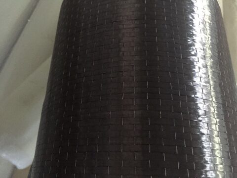
FidStrong manufactures FSC carbon fabric (tf, Ef, and characteristic εfu per grade on each data sheet) and the saturating epoxy that forms the wrap, under ISO 9001, 14001, and 45001 systems. The illustrative calculation uses FSC300 data-sheet values with a hypothetical column geometry; equations follow ACI 440.2R-17 Ch. 12. Confirm every value and the governing load case against the code and a qualified engineer’s design. For flexure use a plate, not a wrap.