Carbon Fibre Bar & Rod for Near-Surface-Mounted Strengthening
Pultruded CFRP in Ø 6–12 mm, bonded into a groove cut in the cover of an existing concrete, timber or masonry member.
What this product is — and what it is not
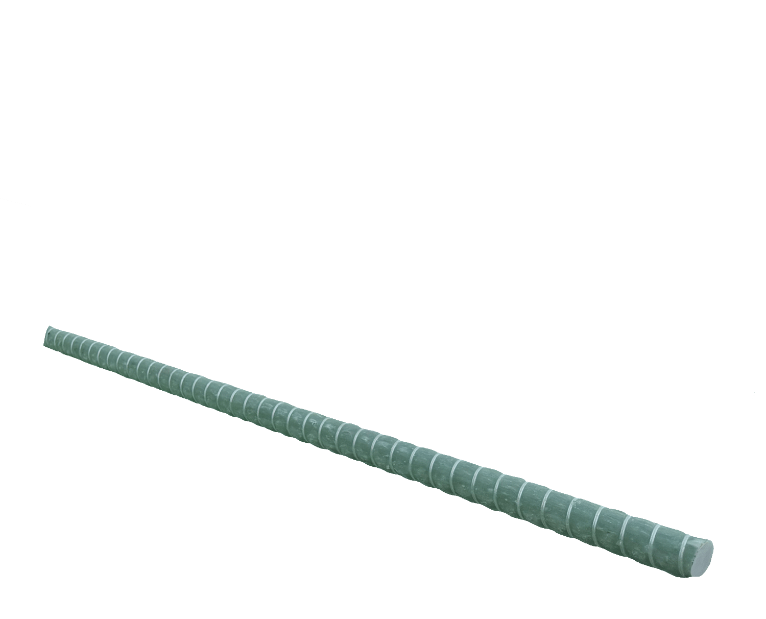
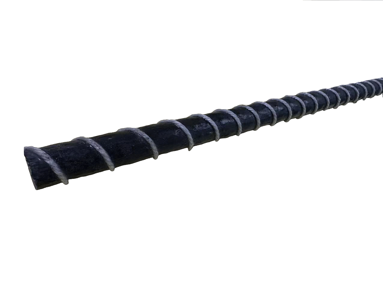
FSB (bar) and FSR (rod) are pultruded carbon-fibre reinforced polymer profiles supplied in Ø 6, 8, 10 and 12 mm. Both datasheets describe them the same way: CFRP laminates designed for strengthening concrete, timber and masonry structures — raising the capacity of a member that already exists, repairing deterioration, or correcting a design or construction defect.
The normal way to use them is NSM — near-surface-mounted: a groove is cut into the concrete cover, the bar is bedded in an adhesive, and the groove is filled flush. The bar ends up inside the cover rather than glued to the face, so it is protected from impact, fire exposure and vandalism, and the finished surface barely changes.
What it is not. This is not a substitute for the reinforcing steel in a new structure. Our two datasheets cover strengthening only — they say nothing about use as primary internal reinforcement, and nothing about marine, tunnel or MRI service. If that is your application, tell us and we will say plainly whether we can support it with test data. We would rather lose the enquiry than sell you a bar against a datasheet that does not cover the job.
| Property | Value |
|---|---|
| Models | FSB (bar) / FSR (rod) |
| Diameter | Ø 6 / 8 / 10 / 12 mm |
| Colour | Black |
| Dry Fibre Tensile Strength | FSB 4,900 MPa · FSR 5,100 MPa |
| Tensile Strength — mean | FSB 2,000 MPa · FSR 2,400 MPa (EN 2561) |
| Tensile Strength — design | FSB 1,670 MPa · FSR 1,750 MPa |
| Tensile Elastic Modulus | FSB 165 GPa · FSR 150 GPa (EN 2561) |
| Elongation at Break | 1.5% (EN 2561) |
| Fibre Content | FSB min 68% · FSR min 65% |
| Glass Transition Temperature | Tg min 100°C |
| Density | 1.6 g/cm³ |
| Packaging | 6 m / 12 m or customised |
| Storage | Dry, out of direct sunlight, −5°C to +35°C |
| Shelf Life | 2 years |
Where an NSM Bar Is the Right Answer
Slabs that have to carry more
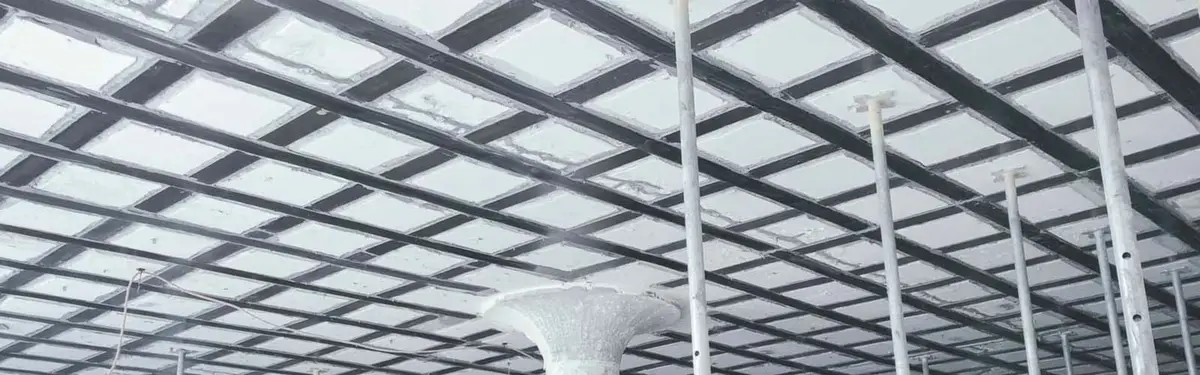
A floor being taken from office loading to storage loading, or a slab that was built light. Grooves run in the span direction, and the finish closes over them.
Beams short on flexural capacity
Grooves along the tension face. Because the bar sits inside the cover rather than on it, the strengthening survives impact and abrasion that would damage a plate bonded to the surface.
Shear at the beam web
Short grooves cut at an angle across the web, bar bedded and filled flush, spaced to the engineer’s detail. A workable answer where a full U-wrap cannot get round the slab.
Timber beams and joists
Both datasheets list timber. A bar routed into the top or bottom of an old joist adds capacity without changing the visible section — useful where the timber is the architecture.
Masonry walls, piers and arches
Bars bedded into raked bed joints or cut grooves. The bar is slim enough to disappear into a joint, so the face can be repointed back to its original look.
Fixing what was built wrong
A member that came out under-reinforced, or a penetration cut through it after the fact. Both datasheets name defect correction as an intended use.
FSB or FSR — and How They Sit Against Steel
| Model | What it is | Pick it when |
|---|---|---|
| FSB | Carbon fibre bar. Mean tensile 2,000 MPa, design 1,670 MPa, modulus 165 GPa, fibre content min 68%. | Stiffness matters more than raw strength. NSM strengthening is usually governed by how much the member deflects before the bar does any real work, so the stiffer bar is the default choice. |
| FSR | Carbon fibre rod. Mean tensile 2,400 MPa, design 1,750 MPa, modulus 150 GPa, fibre content min 65%. | You are strength-limited rather than stiffness-limited — a short groove length, or a detail where the extra 80 MPa of design strength closes the gap. Note the trade: 20% stronger on the mean, but 9% less stiff. |
| Against steel | Carbon fibre bar | What that actually means on site |
|---|---|---|
| Design strength | 1,670–1,750 MPa, against about 500 MPa for B500 steel | About 3.3 to 3.5 times steel, on design values. You will see ‘5 to 7 times stronger than steel’ on competitor pages — and, until this page was rewritten, on ours. That ratio only appears if you compare the dry-fibre number against steel, and nobody can build with the dry-fibre number. |
| Weight | 0.045–0.181 kg/m, against 0.222–0.888 kg/m for the same diameter in steel | Just under one-fifth the weight, diameter for diameter (density 1.6 against 7.85 g/cm³). One person carries a 12 m length of Ø 12. |
| Stiffness | 150–165 GPa, against about 200 GPa for steel | Less stiff than steel, not more. This is the number most people get wrong. The bar is far stronger but slightly springier, so deflection and crack width — not rupture — usually decide how much capacity you can add. |
| Ductility | None. Linear right up to failure, at 1.5% elongation | Steel yields and warns you; carbon fibre does not. Every FRP design code handles this by making sure the concrete or the bond governs, never the bar. |
| Bending on site | Not possible | The resin is already cured. NSM bars are straight and stay straight — which is no loss, because a groove is straight too. |
| Corrosion | None | Real, and it is part of why the bar suits damp interiors and de-iced decks. But our datasheets do not cover marine, tunnel or MRI service as a design case, so we do not sell it on those. |
Both models come in Ø 6, 8, 10 and 12 mm, in 6 m and 12 m lengths or cut to order. Fibre content aside, the two share elongation at break (1.5%), density (1.6 g/cm³) and glass transition temperature (min 100 °C).
Everything on this page is a material property from our datasheets. It is not a design. Groove size, bar spacing, development length and the adhesive all have to be checked by your engineer against the code you are building to — ACI 440.2R in North America, EN 1992-1-1 Annex J in Europe.
Sizes, Weights and Design Tensile Force
Four diameters, weight against steel, and what one bar carries
| Bar Ø (mm) | Nominal area (mm²) | CFRP mass (kg/m) | Steel mass, same Ø (kg/m) | FSB design force (kN) | FSR design force (kN) |
|---|---|---|---|---|---|
| 6 | 28.3 | 0.045 | 0.222 | 47.2 | 49.5 |
| 8 | 50.3 | 0.080 | 0.395 | 83.9 | 88.0 |
| 10 | 78.5 | 0.126 | 0.617 | 131.2 | 137.4 |
| 12 | 113.1 | 0.181 | 0.888 | 188.9 | 197.9 |
Area is the plain circular area πd²/4. Mass uses the datasheet density 1.6 g/cm³, against 7.85 for steel. Design force is the design tensile strength times the area — 1,670 MPa for FSB, 1,750 MPa for FSR. That is the force in the bar itself, and it is an upper bound: in an NSM job the bond between bar, adhesive and concrete normally gives way first, so the force your engineer can count on is set by the groove and the bond length, not by these two columns.
From the headline number to the number you design with
| Model | Dry fibre (MPa) | Mean tensile, EN 2561 (MPa) | Design tensile, EN 2561 (MPa) | Design as a share of dry fibre | Modulus (GPa) | Strain at design stress |
|---|---|---|---|---|---|---|
| FSB | 4900 | 2000 | 1670 | 34% | 165 | |
| FSR | 5100 | 2400 | 1750 | 34% | 150 |
Read the row left to right and the point is hard to miss: the number you design with is about a third of the number in the headline. The dry-fibre figure is the fibre on its own, before it is embedded in resin — it is not a property of the bar and cannot be used for anything. The mean is the average of the test batch, so half the specimens came in below it. The design value is what survives once that spread is accounted for. The last column deserves a second look too: elongation at break is 1.5%, so at its design stress the bar has already used 67% (FSB) or 78% (FSR) of the strain it has.
These are bar properties, not system properties. An NSM scheme fails at the weakest of four things — the bar, the adhesive, the bond to the concrete, or the cover splitting away. The bar is almost never the weakest. Ask your engineer which one governs before sizing anything from this table.
Installing an NSM Bar in Six Steps
Find the steel before you cut
Scan the cover with a rebar locator and mark the existing bars. A groove that nicks a stirrup or a main bar has done more harm than the strengthening will undo. Set the groove lines out to miss them, and if that turns out to be impossible, say so before cutting rather than after.
Cut the groove
Dry-cut diamond blade with vacuum extraction, two parallel passes, then break out the middle. The common rule of thumb is a square groove about 1.5 times the bar diameter, but take the dimension from your engineer — it depends on the adhesive and on the cover you actually have. The groove must stay within the cover: it is a groove, not a chase into the structural section.
Clean it properly
Blow the slurry and dust out with oil-free compressed air, then let it dry. Adhesive bonds to sound concrete, not to saw dust. Check the substrate is dry — the plastic-sheet method in ASTM D4263 tells you whether moisture is rising, though it will not give you a percentage.
Half-fill, bed the bar, top up
Fill the groove about half way with the anchoring adhesive, press the bar in until adhesive rises around it, then fill flush. Working the bar slightly as you seat it drives trapped air out. The bar must end up surrounded by adhesive on all four sides, not resting on the bottom of a dry groove.
Respect the working time
Adhesive working times are quoted at 23 °C for a small mix. On a hot slab, or with a large batch in one bucket, you get considerably less. Mix what you can place, and place what you mix.
Leave it alone while it cures
No load, no drilling nearby, no vibration until the adhesive has reached the cure its datasheet states. Then make the surface good. Because the bar sits inside the cover, the finished member looks almost unchanged — usually the reason NSM was chosen over a bonded plate in the first place.
Frequently Asked Questions
Can I use this instead of steel rebar in a new structure?
Our datasheets do not cover that. Both describe FSB and FSR as CFRP laminates for strengthening existing concrete, timber and masonry — they say nothing about primary internal reinforcement, and nothing about marine, tunnel or MRI service. Some FRP bars are qualified for internal reinforcement under specifications such as ASTM D7957 for glass fibre. Ours are not sold on that basis. Ask us and we will tell you plainly what test data exists, rather than guess.
Why is the design strength so much lower than the 4,900 MPa on the front of the datasheet?
Because 4,900 MPa is the dry fibre, before it is embedded in resin. The bar is fibre plus matrix, and the matrix carries almost none of the tension. Measured as a bar to EN 2561, FSB averages 2,000 MPa, and the design value after allowing for batch spread is 1,670 MPa — about a third of the headline. Every honest CFRP datasheet has this gap. The ones that print only the big number are hoping you will not ask.
FSR is stronger than FSB. Why would I ever pick FSB?
Because FSB is stiffer: 165 GPa against 150 GPa. In most NSM strengthening the member deflects long before any bar is near its strength, so stiffness is what limits the load you can add — and the extra strength in FSR never gets used. Pick FSR when a short groove or an awkward detail makes strength the binding constraint.
Can you bend it to shape?
No. The resin is cured, so the bar is straight and stays straight. It cannot be bent on site and we do not supply bends. For NSM this is rarely a problem, because grooves are straight.
What adhesive goes in the groove?
An epoxy anchoring adhesive. Our FIS FIX is the usual pairing and we will quote it alongside the bars. The choice is not cosmetic — in almost every NSM scheme the bond, not the bar, is what governs, so the adhesive is doing at least as much of the work as the carbon.
How does it behave in a fire?
Glass transition temperature is a minimum of 100 °C, and above the glass transition both the matrix and the adhesive soften, so the bar stops being able to transfer force. Sitting inside the concrete cover helps, which is a genuine advantage over a plate glued to the face, but it is not a fire rating. A fire case needs a designer who assumes the strengthening is lost and checks that the unstrengthened member still carries the fire load combination.
What lengths, and what about storage?
6 m and 12 m straight lengths as standard, or cut to your groove lengths. Store dry and out of direct sun, between −5 and +35 °C. Shelf life is two years.
Do you have test reports, or just the datasheet?
The datasheet carries the EN 2561 tensile and modulus values, mean and design, for both models. If your engineer needs the underlying report, ask and we will request it from the production line — rather than tell you it exists when we have not seen it.
Documents & Downloads
Two datasheets, one per model
TDS-FSB for the bar and TDS-FSR for the rod. Each carries the dry-fibre, mean and design tensile values, the modulus to EN 2561, fibre content, elongation, density, glass transition temperature, packing and storage. Both are on this page.
What is deliberately not in them
There is no bond-strength figure, no development-length table and no fire rating. Those belong to the adhesive and to the design code, not to the bar. If a supplier hands you a finished NSM design taken straight off a bar datasheet, treat it as a warning sign rather than a service.
Request a Quote
Send the member, the extra capacity you need and the groove spacing your engineer has in mind. We will come back with the diameter, the model and the metres — and with the datasheet, so your engineer can check our numbers instead of taking our word for them.